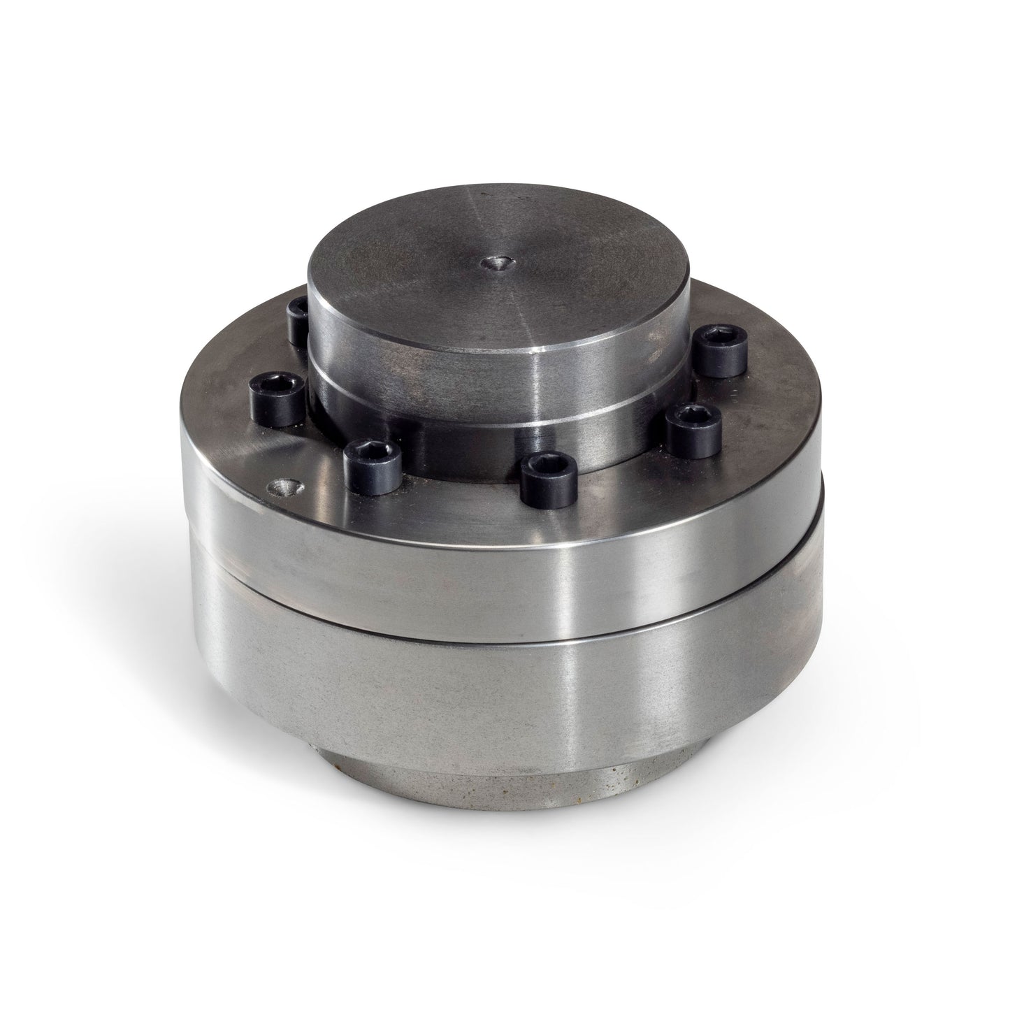
N-EUPEX A 180
N-EUPEX A 180
- Series: N-EUPEX MD10.1
- Scope of supply: Complete coupling, unbored / pilot bored
- Please note that a bore is required to install the coupling.
Couldn't load pickup availability
About N-EUPEX Pin Coupling
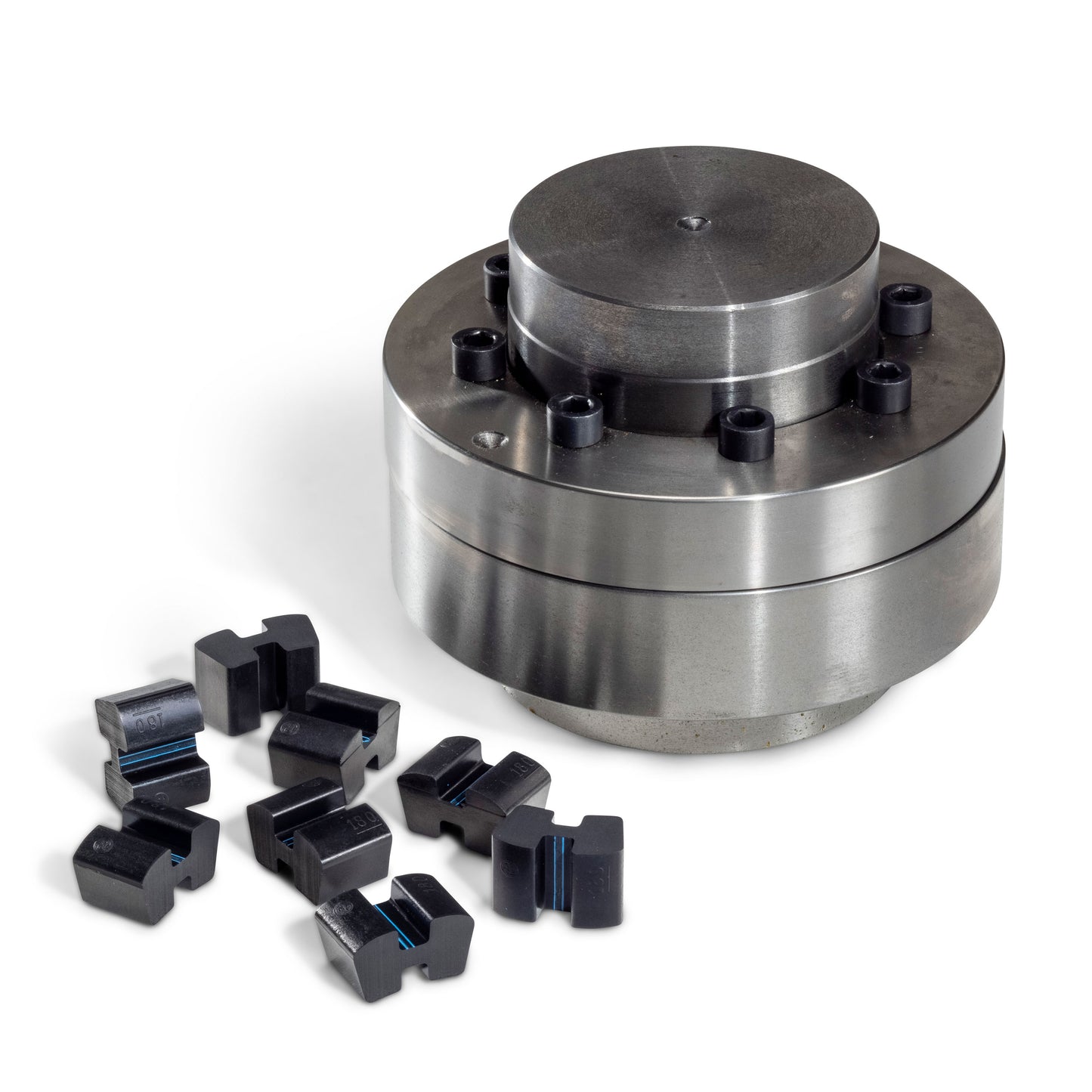
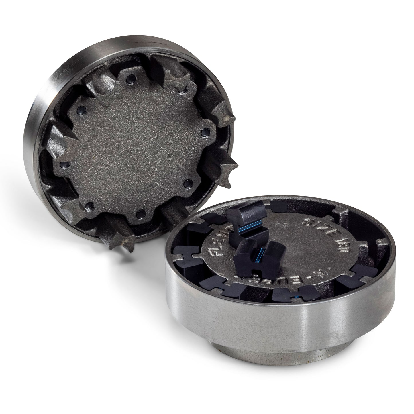
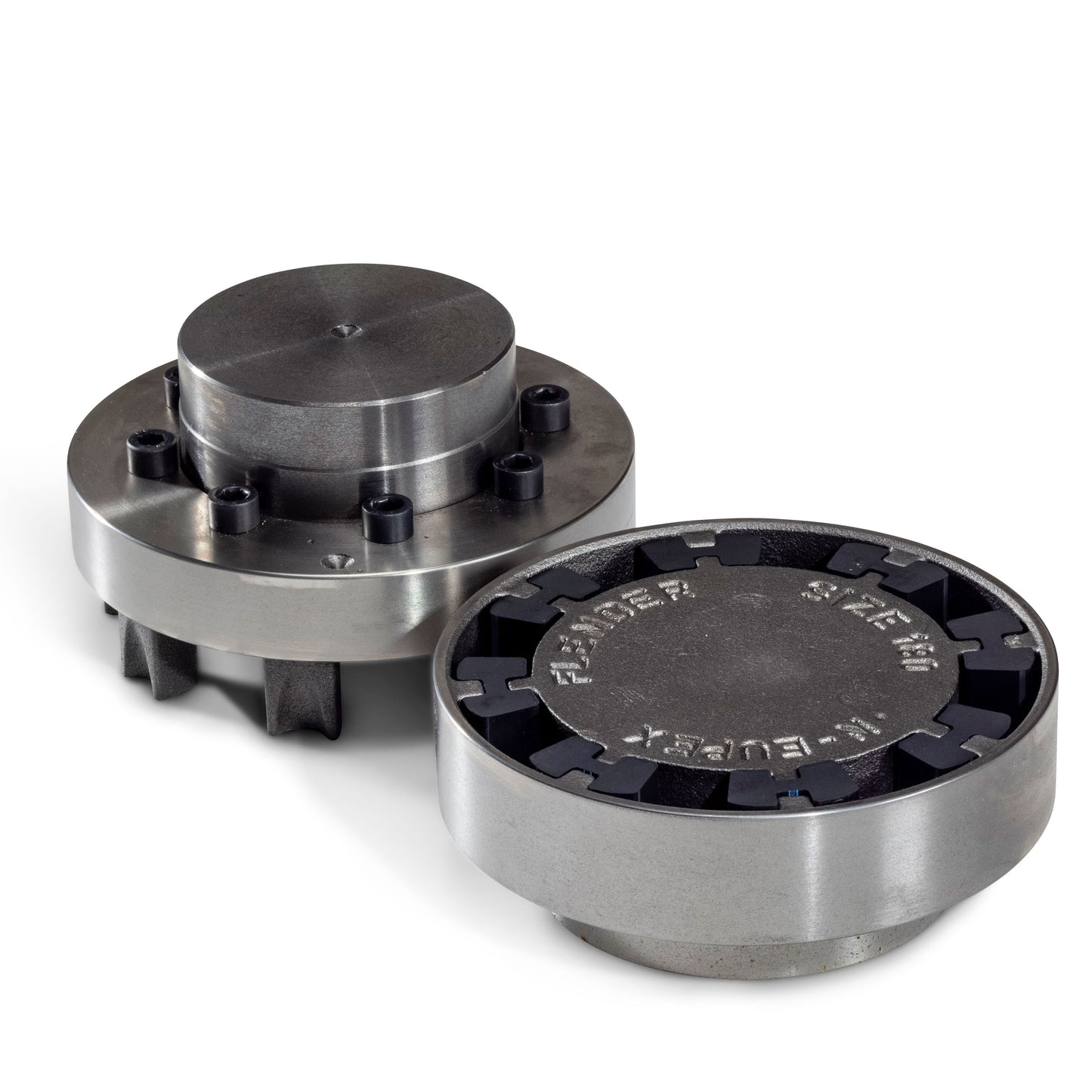
Due to their torsional flexibility N-EUPEX couplings offer the possibility of moving critical torsional vibrations from the operating area of the mechanical equipment in such a way that no negative effects on the drive train are to be expected. N-EUPEX couplings are made of high-quality cast iron. The flexible elements made of synthetic rubber (buna N) are available in different degrees of hardness for many applications. Metal pins and flexible elements are so designed that no wear occurs when properly fitted.
Application field
Widespread use in all mechanical engineering, both on the motor side as a high-speed coupling, e.g. pump, fan or compressor applications as well as at high torques for connecting gear units and driven equipment, e.g. mills.
Advantages of the product
- Torsionally rigid and damping pin coupling to be used universally for compensating shaft misalignments
- Maximum operational reliability, since fail-safe
- Suitable for plug-in assembly and simplified replacement of elements in the type consisting of three parts
- Dynamic adaptation by selection of elastomer hardness
N-EUPEX A 180 Detailed information
| Product | ||
| Series | N-EUPEX MD 10.1 | |
| Type | A | |
| Size | 180.0 | |
| Scope of supply | Complete coupling | |
| Basic data 1) | ||
| Rated coupling torque | TKN | 880 Nm |
| Maximum coupling torque | TKmax | 2640 Nm |
| Coupling overload torque | TKOL | 3080 Nm |
| Alternating coupling torque | TKW | 132 Nm |
| Maximum coupling speed | nKmax | 3800 min-1 |
| Permissible ambient temperature | Ta | -30°C ...80°C |
| Permissible axial misalignment Ka 2) | ∆Ka | 2 mm |
| Permissible radial misalignment Kr 3) | ∆Kr | 0.3 mm |
| Permissible angular misalignment Kw 3) | ∆Kw | 0.1 ° |
| Torsional stiffness, dynamic 4) | CTdyn | 46 kNm/rad |
| Weight | 16.3 kg | |
| Connection 1 part 1 5) | ||
| Hub design | Unbored / pilot bored | |
| Hub diameter | 125 mm | |
| Connection 2 part 2 5) | ||
| Hub design | Unbored / pilot bored | |
| Hub diameter | 108 mm | |
| Product-specific options | ||
| Elastomer | Packs NBR 80 Shore A | |
| Preservation | Cleaning emulsion - indoor storage up to 3 months | |
| Balance state | ||
| Balancing quality | G 16 / n=1500 min-1 | |
| Corrosion protection | ||
| Paint coat 3) | Without paint finish | |
Note
1) The formula symbols are defined here.
2) The permissible axial offset is applicable for offsets that slowly occur, e.g. as a result of thermal expansion of the coupled shaft.
3) Permissible shaft offset at rated speed nN = 1500 min-1.
4) Torsional stiffness at 0.5 * TKN, excitation amplitude of 0.1 * TKN with 10 Hz, ambient temperature 20°C.
5) The orderer is responsible for verifying the design strength of the shaft-hub connection.
Technical data are subject to change! There may be discrepancies between calculated and rating plate values.
